Aquecimento por induo Diagrama de circuito Projeto de circuito Circuit Diagram Induction Heating Circuit Diagram Working And Applications. A Comprehensive Overview Of Power Converter Topologies For Induction Heating Applications Vishnuram 2020 International Transactions On Electrical Energy Systems Wiley Online Library. The Schematic Diagram Of Induction Heating System Scientific.

Inductive Heating of Metal Induction Heating Circuit Diagram. The setup used for the induction heating process consists of an RF power supply to provide the alternating current to the circuit. A copper coil is used as inductor and current is applied to it. The material to be heated is placed inside the copper coil. Typical Induction Heating Setup
How to Design an Induction Heater Circuit Circuit Diagram
The following PCB design for the above IGBT induction heater circuit was provided by an avid reader of this blog Mr. Атанас. 220V AC to 220V DC Bridge Rectifier Circuit with Safety Lamp The Choke L1. The design of the choke L1 used in the above full bridge IGBT induction heater circuit can be witnessed in the below given image:
![[DIAGRAM] Wiring Diagram For Induction Heating Circuit Diagram](https://i.stack.imgur.com/dSj1P.gif)
Building an Induction Heater Circuit: Step-by-Step Guide. Building an induction heater circuit is a complex process that requires careful planning and understanding of the principles behind induction heating. By following a step-by-step guide, you can create a functional induction heater that can be used for a variety of applications.

Induction Heater Circuit Using IGBT (Tested) Circuit Diagram
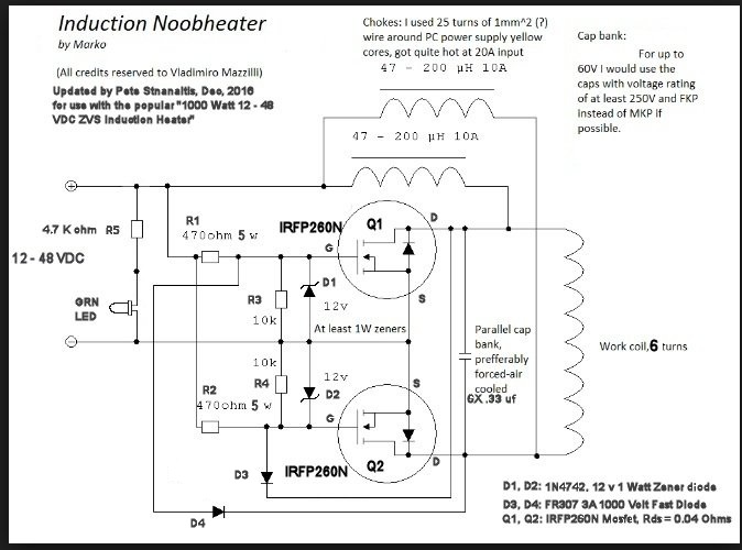
Induction heaters are used to heat conductive materials in a non-contact process. Commercially, they are used for heat treating, brazing, soldering, etc., as well as to melt and forge iron, steel, and aluminum. This Instructable will walk you through the construction of a high-power (30kVA) heater, suitable for melting aluminum and steel. The schematic diagram of an induction heater typically includes a high-frequency oscillator, a power amplifier, a coil, and a control circuit. The oscillator generates a high-frequency signal, usually in the range of tens or hundreds of kilohertz. The power amplifier then amplifies the signal to a level suitable for heating the workpiece. In the above induction heater circuit diagram we can see the MOSFETs gates consisting of fast recovery diodes, which might be difficult to obtain in some parts of the country. A simple alternative to this may be in the form of BC547 transistors connected instead of the diodes as shown in the following diagarm.
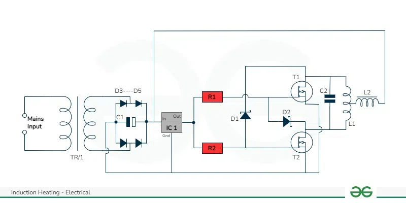
This diagram shows the addition of 2 diodes to the circuit so that it can be linked to one of our PWM Control circuits for adjusting the power of the induction heater. The duty control of the pwm circuit is inverted compared to the output power of the heater. which means setting the duty to 100% will turn off the heating.
