How to Make a RFID based Attendance System Circuit Diagram This is where an RFID-based attendance system comes into play. By leveraging the power of RFID technology and Arduino, we can create a system that is both reliable and easy to use. This blog post will guide you through the process of building your own RFID-based attendance system, complete with detailed explanations and full Arduino code. The RFID-based office attendance system consists of three main components: Arduino with RFID Scanner and Servo Lock: An Arduino board is utilized to control a servo motor that acts as a door lock mechanism. The system reads RFID card data and grants access by unlocking the door with servo motor if the card is approved. This command will give our "attendance_admin" user full privileges on any table within our database. GRANT ALL PRIVILEGES ON attendance_system.* TO 'attendance_admin'@'localhost'; Before we create our tables, we need to utilize the "use" command so that we are directly interacting with the "attendance_system" database.
with the RFID system. This system consists of an RFID reader and a tag which can be developed as a student attendance machine during lectures.[2] Several researchers have conducted research on the digital student attendance system. The system designed is a portable attendance system that uses an RFID tag to identify student attendance and is In this project we have designed RFID Based Attendance System using Arduino UNO and RFID MFRC522 Module. circuit design. Schematic diagram. circuit_xnsmkov7uh_IhD3g2prQv.jpg. circuit_xnsmkov7uh_IhD3g2prQv.jpg. Comments. Only logged in users can leave comments. login. team_chkr.

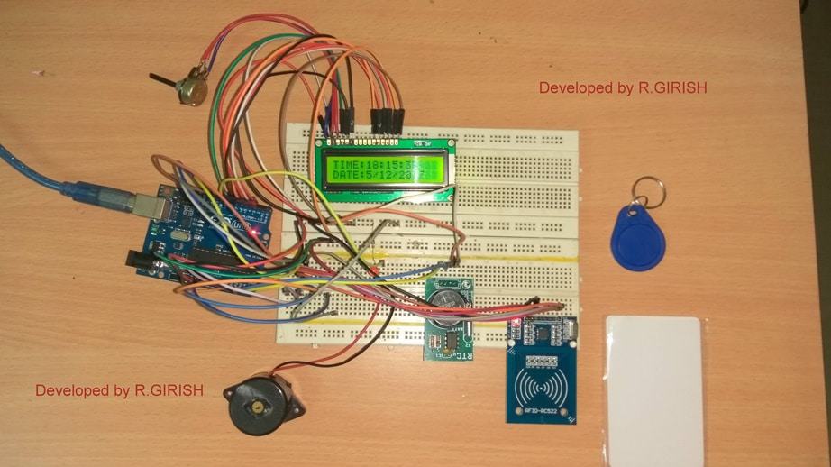
Based Attendance System Circuit Diagram
A. Hardware design . This system consists of automatic attendance system for both students and professor. While entering the class room both the student and professor have to mark their attendance using their RFID cards. This attendance will be forwarded to a central computer after processing it through the microcontroller where it will be RFID Attendance System Circuit Schematic. RFID Attendance System GPIO Pins Utilized. Preparing the RFID Attendance System Database. 1. Now before we go ahead and program our RFID attendance system, we must first prepare and set up the MYSQL database. This database is where we will be keeping track of each RFID cards attendance and who owns that *RFID SDA to arduino Digital pin D10. *RFID SCK to arduino Digital pin D13. *RFID MOSI to arduino Digital pin D11. *RFID MISO to arduino Digital pin D12. *RFID GND to arduino GND. *RFID RST to arduino Digital pin D9. *RFID 3.3V to arduino 3.3V. RTC module connections. *RTC module SCL to arduino A5. *RTC module SDA to arduino A4.

First, we'll set up the RFID component based on the system described in the Viral Science Creativity tutorial: By following these steps, you may create a two-step attendance system that combines
