Programmable Logic Controller Circuits Using Digital Logic Design Circuit Diagram PLC Inputs and Outputs (I/O) PLC Ladder Logic; Programmable Logic Controllers (PLCs) are small industrial computers with modular components designed to automate customized control processes. PLCs are often used in factories and industrial plants to control motors, pumps, lights, fans, circuit breakers and other machinery.
Key learnings: PLC Definition: A programmable logic controller is a specialized computer designed to operate in industrial settings, managing and automating the mechanical processes of factories and plants.; Functionality: PLCs handle tasks like timing and logic operations, significantly streamlining industrial processes.; Programming Flexibility: The programming of a PLC can be altered to

PDF Design Projects in a Programmable Logic Controller (PLC) Course in ... Circuit Diagram
The PLC course is a junior/senior level course in a four-year electrical engineering technology institution. The main objectives of the course are: Identify and explain the purpose of the parts of a programmable logic controller Use basic PLC relay instructions to write, debug and troubleshoot ladder logic programs
A PLC's primary function is to control the functions of a system utilizing the underlying logic that it has been programmed. PLC s (Programmable Logic Controllers) is common in industry today. Proper PLC system design can give many years of service to a machine or process while also increasing efficiency & profitability for the company that
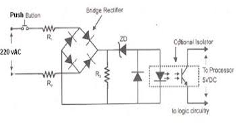
Build Your Own Programmable Logic Controller Circuit Diagram
Ladder Logic Diagram. The most commonly used PLC programming language is the Ladder Logic Diagram. The reason for its popularity is that Relay Logic Diagrams were closely resembled by the Ladder Logic Diagrams. When the PLC was invented, designers found a way to use the existing knowledge of the Relay Control System designers for programming
Logic Circuit Must-Haves. You can easily configure an AND circuit by wiring two switches or contacts in series, providing only one path for current to take. Take the output point from one switch and wire it to the input point of the other. The output of this circuit can then be used to turn on a light, fan, pump etc.
